Title.
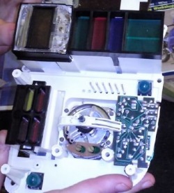
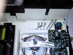
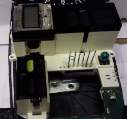
Above is how the gear position indicator connectors should look ( if they do then you should try the transistor replacement ) . All straight and solid.
Title.
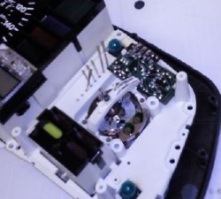
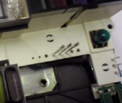
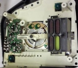
this is how mine looked. (neutral worked when i viewed and bought nice green , by time id got home nothing.The pegs were wobbly and obviously loose. Picked up a for spares only set off ebay for 99p to see what had happened and was immediately obvious. ( thoughts behind purchase were so i could dismantle and in process not screw mine up.)
Title.
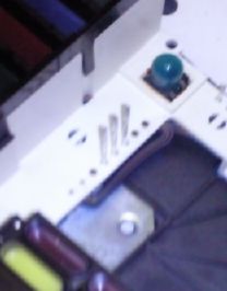
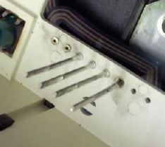
when i removed the tacho layer ( 3 screws ) this is what i was left with 3 pins still intact. If you can see the 3 darker holes thats where the pegs were attached.
Title.
here are the missing pieces!!!
Title.
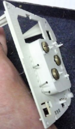
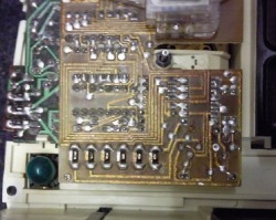
with this pic ( before layers ) you can see exactly how bad the pins were in place,no wonder id got nothing.
Title.
another view of pins left with corrosion evident
Title.
Neede to be put back in place. Decided to go the old route solder and a metal connector rod. Firstly i cleaned up all the corrosion on both bits of pins( the snapped bits and the ground pins ) (the bits that were still attached to the circuit board more like a rivet to be honset.)
Th pins are hollow so was easy progression to realise my idea would work!You just needed something small enough yet big enough so no extra heat goes into plastic circuitry behind. yet the solder amount can fill void and set solid so full conductivity.
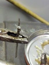
After ages debating wife said sewing needles!! Snapped in half to fit! So in picture the needle has been soldered into place. So when you go to put it in board you can just use solder gun to heat it up and will form solid anchor connection to its previous other bit.
Th pins are hollow so was easy progression to realise my idea would work!You just needed something small enough yet big enough so no extra heat goes into plastic circuitry behind. yet the solder amount can fill void and set solid so full conductivity.
After ages debating wife said sewing needles!! Snapped in half to fit! So in picture the needle has been soldered into place. So when you go to put it in board you can just use solder gun to heat it up and will form solid anchor connection to its previous other bit.
Title.
this is the first pin in place ( scary but theory works!!) solid . tested with multimeter and yes works no resistance so "bonded" well!!)
Title.
all the pins in place. just repeated same method.all solid and conductive.
Title.
Added rev counter layer back on top. No messin just slid into place pins still solid.
Title.
Gear board back in place.pins just slid into place. but the theory has now got to be seen for praticality.
Title.
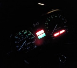
YES!! my neutral lights back !! solder and some sewing neeldes!!! goes out when changes gear!! As an added bonus the gear indicator LCD also changes ( but seeing as that cant have worked for years and screen only had a little blodge visible ) it changes shape splodge to splige with gear selected!! Will drive me nuts but for now it can stay at least the circuits are working and im down nothing! Well 80p for wifes sewing needles to be replaced. Solder already in.
If this isnt your problem and want to know more try
http://k100rt.aforumfree.com/
theres loads of advice. Including the gear position transistor which could make this more understandable. I tried that first but it didnt work for me.
ride safe
pete
If this isnt your problem and want to know more try
http://k100rt.aforumfree.com/
theres loads of advice. Including the gear position transistor which could make this more understandable. I tried that first but it didnt work for me.
ride safe
pete
